
Electronics
Been getting into electronics and embedded computing a bit more lately. Rather than continuing to drift the content of the Computers and Programming page off-topic, this sort of thing will go here now.
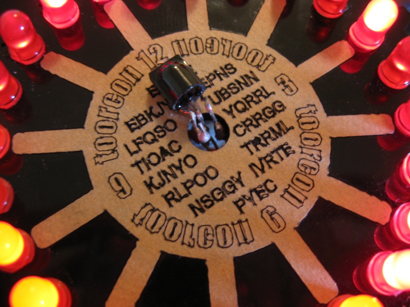
Toorcon 12 Badge Hack
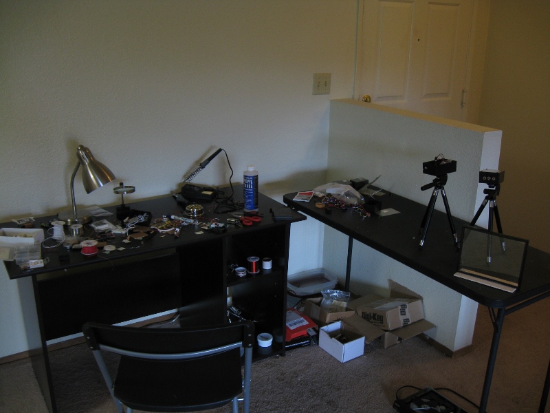
Toorcon 12 was awesome. The badges this year were really basic round plastic discs with component holes drilled around the edge and a larger hole in the center. This left the hacking opportunities wide open and lots of folks had a go at it. I was really impressed by all the folks that had no prior experience with electronics/soldering huddled around the hardware table learning. Everyone was all about helping each other out and the tools/components available on the table were plentiful. After registering on Friday night and going home, I sat down at my makeshift electronics lab and got to work...
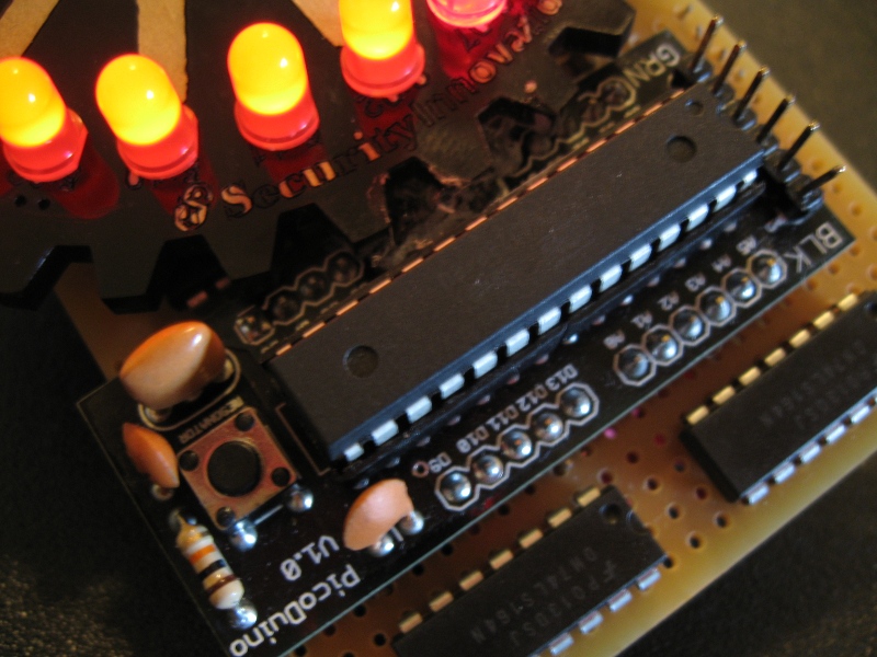
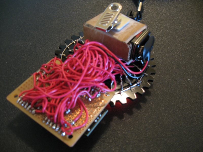
The first thing that I was curious about was making the Picoduino kit that I bought at Next Hope work. So I managed to get it programmed using an FTDI cable to blink an LED; sweet. At that point, remembered having some 74LS164N 8 bit shift registers that I picked up on a whim. Some googling got one of these working with the picoduino. The result was being able to individually control 8 LEDs using only 2 digital i/o pins (arduino has a total of 14 vs. the 24 LED places on the badge). At this point its something like 1AM..the answer was clear: sleep is for the weak. So I soldered what I had together on a protoboard and put the LEDs around the badge. Working one shift register (and 8 LEDs) at a time, using 24ga solid wire, I put the everything in place. When doing is sort of thing, its very important to test your work constantly. I reprogrammed and tested roughly every 2 LEDs; you do not want a broken, bridged, or miswired connection in this ratsnest to troubleshoot. After getting the whole thing together and beating my head against some really simple binary conversion/mapping code, it was over; the picoduino could individually address each LED and run off a voltage divided 9V. By chance, I happened to have all of the parts I needed in my little spare parts box: including exactly 24 mismatched red LEDs.
So its probably 5AM at this point and I get feature-creep syndrome. I finished a laser microphone system (working on quality, stay tuned) recently (thanks to the article on LucidScience) so was thinking about infrared. Then it was all clear, this thing could be like a TV. Changing the channel could change the patterns of lights, pause, play, rewind, volume for speed, omg-awesome-must-do! The problem was that I only had one infrared phototransistor already built into the laser mic. Then I noticed my DVD player sitting below my TV. Now I don't know how you guys feel about it, but a laser eavesdropping system is wayyyy cooler than a lame DVD player. So it got to donate some components to my parts box including the IR receiver module. This was then soldered to one of the analog input pins; no easy task considering the wiring in place. I tried for about an hour to receive and decode the infrared codes from my Sony remote control manually. In the end, I just grabbed an awesome infrared library for Arduino (link is below). You set the IR pin in a variable and then just call a function and it spits back the received code or nothing; really slick library. Some googling got the codes for my remote. At the end of it all, I ended up just making the channel button flip between 5 modes and the volume speed up/down the patterns. I couldn't get power-on/off to work for some reason, it acts funny. If you guys see a bug, be sure to let me know. Instead of clearing all LEDs and stopping, it sort of pauses leaving a single LED on until pressed again and resuming the pattern.
So then I shower and head back to Toorcon. It turns out there is a badge hacking contest; neat! I spent the rest of the time running around showing my hack off to anyone that would listen. I was the only one that wasted all the time getting all the LEDs flashing and patterning so folks kept asking about it. Once that happens, you gotta do the whole demo :-) Another dude came really close to the same level of LED control with his hack. He populated the LEDs in the shape of parentheses and used a full arduino board attached below to flash a cool pattern. H1kari was running around shooting videos for the badge hacking contest and grabbed me up to make a clip. During the closing remarks, they showed the top 6 badge hacks and voted by round of applause. Holy crap. I was not expecting the response at all, but the whole place went nuts over the badge. This group is crazy-smart and I respect all of these folks so much, so it was really cool to see that everyone was as excited about this thing as I was. So I won the contest and got some prizes in the form of books from No Starch Press. I really want to thank geo, h1kari, and all the rest of the staff; you guys rock. Oh yeah, thanks for the gangster Toorcon flask :-)
Source code: [toorcon.pde]
Ken Shirriff's Arduino Infrared Library: [link]
Schematic: [tcscat.JPG]
![[tcscat.JPG]](images/tcscat.JPG)
Proxmark3 LCD
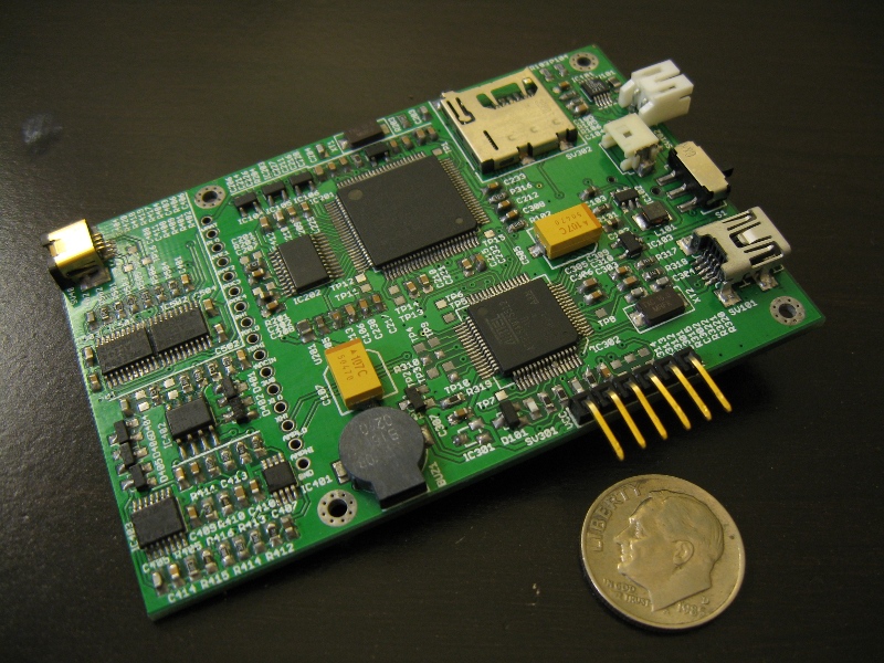
So when Null Space Labs was getting a batch PCB order together for a device called a Proxmark, I wasn't sure if I'd be able to pull it off. Ended up getting in on the order anyway. After ordering around $150 worth of surface-mount components, having never done SMD soldering, I headed up to the space and got to work. Thanks to all the folks up at NSL for helping me work out the kinks and get used to soldering tiny stuff, especially mmca and charliex. To anyone else looking to build one of these, READ THE WIKI.
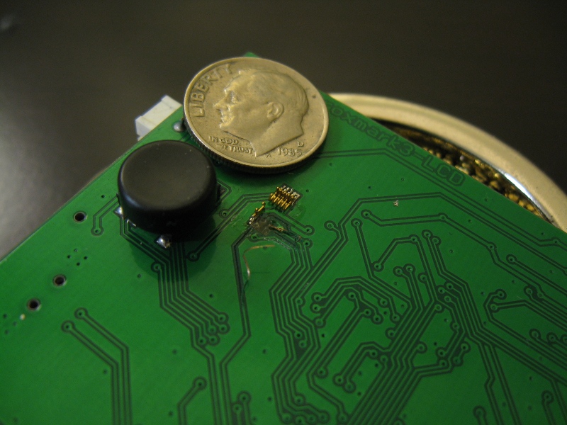
The Proxmark3 LCD is a fancy variant of the more popular Proxmark3. These devices are essentially the swiss army knives of the RFID world. RFID is a technology used primarily for authenticating users of a system via relatively short range radio communication. The tags are typically powered remotely by the RFID reader itself and thus need no batteries. You may have seen this sort of system protecting doors or enforcing toll road "SpeedPass" lanes. Proxmarks allow the user to read, analyze, simulate, and clone a huge variety of RFID tags. So far, I've been able to read and decode a 125 Khz EM4100-series passive tag. Haven't gotten hold of a high-frequency tag to test yet, but simulating/cloning the LF tag is not working yet; must troubleshoot more. I did make a big mistake when assembling the device, though. While trying to remove an incompatible LCD (cellphone screen), the connector ripped the traces off the circuit board. I'll have to jumper the connections with magent wire or properly rebuild the traces on the PCB to make the screen function.
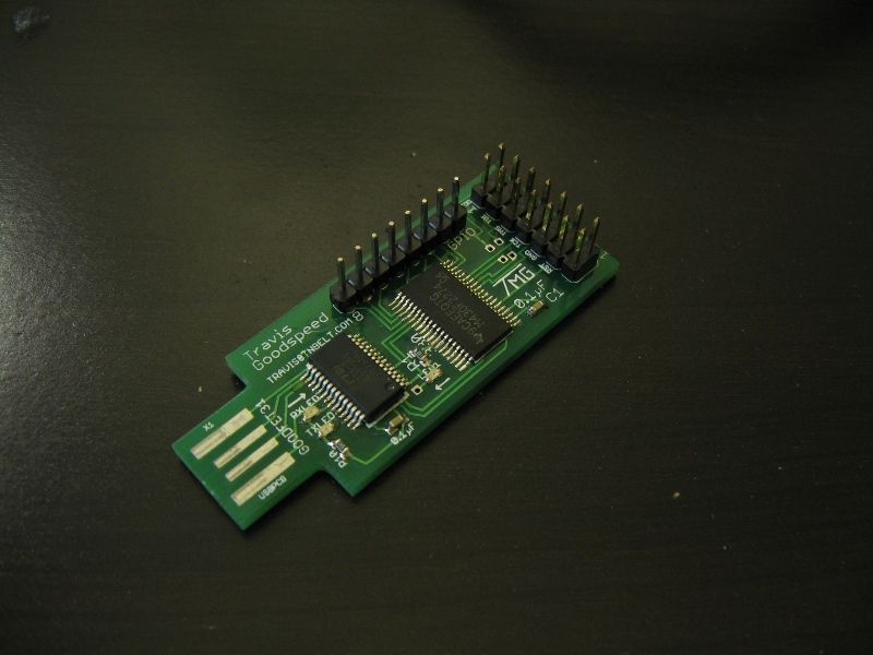
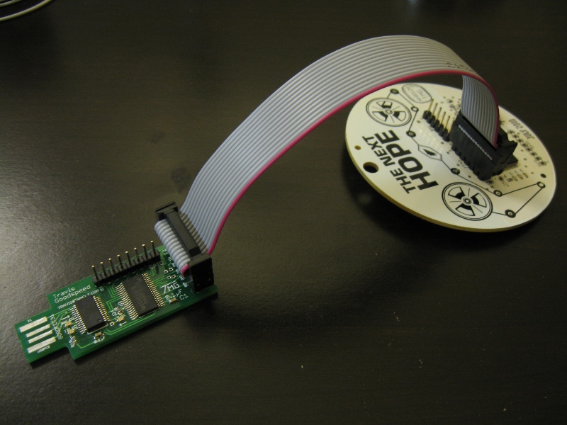
On the electronics side, I also built a GoodFet. These are versatile little PCBs that plug directly into a PC's USB. Once set up, they allow the
computer to communicate with various microcontrollers for programming. I've used it to dump the firmware via JTAG from my
Next Hope badge so far.
Arduino Baby Steps
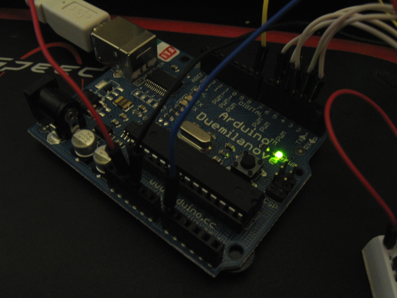
I finally broke down and bought an arduino and some bits to go with it. For those that don't know, the Arduino is an insanely popular open-source microcontroller board. You use the built-in USB interface to load code into it which you write and compile in a C-like language on the connected PC. Its pretty much like having a tiny programmable computer with a bunch of digital and analog inputs and outputs available to it. There have been tons of cool projects made with these things; check out Hack-a-Day for examples. I've been programming and into electronics for years so I figured it was time to combine the two and learn the microcontroller side. These things are really easy to code for and setup was a breeze.
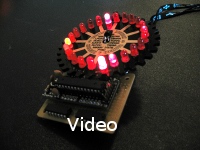
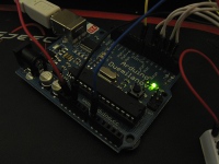
The picture on the left links to a little video of how I've been fiddling with it in the first couple of hours after arrival. Already I'm glad that I
ordered the nice jumper wire bundle and irritated that I didn't order a normal sized breadboard. This one is made to stack on top of a prototyping board
that itself stacks onto the Arduino. The prototyping board pretty much just extends the I/O and power headers up and gives you a clear space in the middle
for circuit building (that tiny breadboard being a good fit). I haven't build this extender board yet (came as a kit), but I should be able to find some
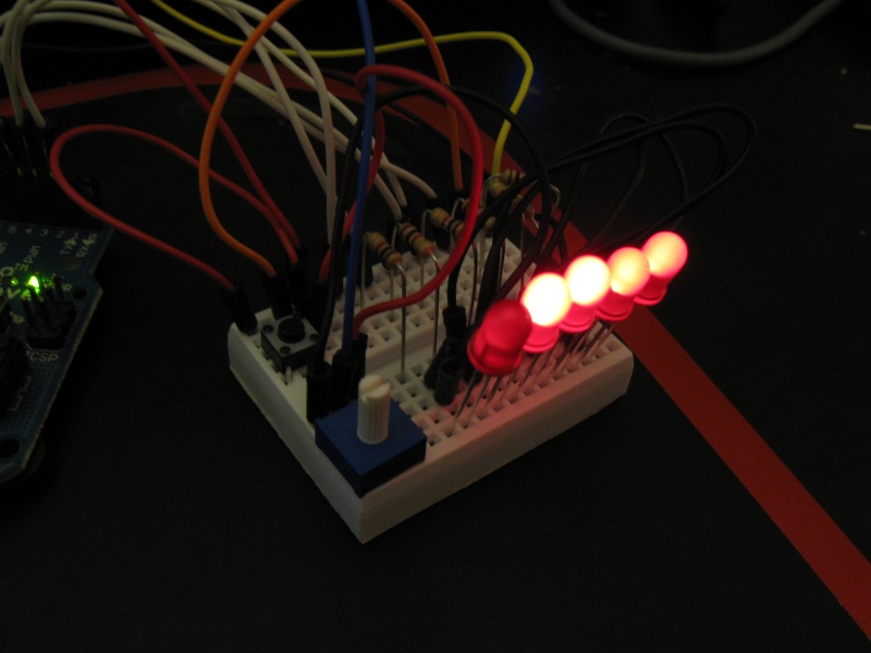
free time at work to solder it. Anywho, the little project in the video counts in binary up to 31 and then resets. If you hold down the push button, it goes
into a bouncing ball mode. Adjusting the potentiometer changes the speed of both modes. If you folks have any ideas for stuff to build; especially
if related to security let me know.