
Modern OpenGL : Matrices
It is time to step away from the code a little and look at some theory. Specifically we'll be learning a little bit about linear algebra and how it is used in OpenGL programming and realtime 3d in general. I am not a big fan of this fancy booklearnin' math stuff, but it is necessary to understand the basics. Hopefully, this page can help the folks out there that struggle with this stuff (myself included). When writing 3d applications, our main goal is pretty humble: turn points in 3d space into 2d points on the screen. Pretty boring, right? Now, once we can do that, we can fill in the space between these points with all sorts of sexy effects. For now, though, we need to get the triangles (which all 3d objects are made of) onto the screen as points. Most of what we talk about on this page will be implemented in the vertex shader.
Object Coordinates
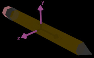
Our journey begins with coordinates in object space. Lets say that you are building a 3d pencil in a modelling program such as Blender. The pencil's center is sitting on the origin ( 0, 0, 0 ). We don't care about where the object will be placed in the world later. It doesn't matter if it ends up in a drawer, on the floor, or in a volcano. As we create the vertices and triangles and make up the pencil, we consider it the center of the universe. The coordinates of these vertices/points are said to be in the object space of the pencil. The X coordinates that fall to the left of the object's center are negative and those to right are positive. We use this coordinate system because it makes it easy to work with the individual points of an object. When loading this data into our program, we can use the origin as a reference for the object's "center" (for positioning, rotation, etc..).
World Coordinates

Remember when I wrote something about not caring about our pencil being in a volcano? Well, at some point that placement information becomes important. When a vertex's coordinates are in world space, it means that they are in relation to the center-of-the-universe(tm). Where is the center of the universe, you ask? It's just the origin (0, 0, 0) in world space coordinates. If an object's center in world space is at (0, 1, 0), that might mean that it is floating 1 meter above the center-of-the-universe (origin). Meanwhile, its topmost vertex might be sitting at (0, 1.2, 0). As an aside, this vertex's object space coordinates would be (0, 0.2, 0).
Now, because our object has decided to join the world community and stop being so self-centered, we need a way to transform its vertices' object space coordinates to world space. We accomplish this feat using transformation matrices. A matrix allows us to transform coordinates from one space to another. The turn those lame object coordinates in world coordinates, we build a model matrix for our pencil. This is a 4x4 matrix that holds information about the pencil's position, rotation, and even scale in the world. By multiply the xyz object coordinates of each vertex in the pencil by this model matrix, we end up with the cooresponding world coordinates for those points.
Eye Space
Alright, now you've constructed a massive world full of pencils and volcanos (and hopefully something more interesting). One thing that is missing here is...a camera. THERE IS NO CAMERA IN OPENGL! Ok, maybe that was a little harsh, but its technically true. What we actually need is a way to transform these world coordinates into eye space coordinates. Eye space is a coordinate system which has the "virtual camera" at its origin. This fake camera is pointed toward the negative Z axis. In other words, vertices that are further away have a more negative Z component. Positive X points to right and positive Y points up. The tool we have to use to transform all of this points in the world into this new eye space is the view matrix. Just like how the pencil's model matrix defines how the pencil is placed and oriented in relation to the origin of the world; the view matrix defines how the origin of the world is placed and oriented in relation to the "virtual camera" (origin of eye space). By manipulating this view matrix, we can control where the viewpoint is and in which direction it is pointing. We aren't actually moving a camera around, however, we are actually moving all of these world point around such that they revolve around the virtual camera.
Clip Coordinates and the Screen
Now the coordinates of all the points in our world are in reference to the virtual camera. But right now, our "camera" is really just a point and orientation in 3d space. We need a projection matrix and viewport parameters to turn this stuff into actual 2d points on the screen. The projection matrix holds information like how close points in front of the view can be (and still be drawn). This is called the near plane and its close cousin in the projection matrix called the far plane is analoguous to the "draw distance" setting found in computer games. The projection matrix also defines parameters like how wide the camera lens is (called field-of-view). The viewport parameters tell the video card how our final image should be mapped onto the screen itself. Resolution, fullscreen, windowed, etc.. are important here. Once you hit clip space while writing your vertex shaders, you can't really go further. After you make that final transformation using your projection matrix, your job is finished.
Transformation Overview
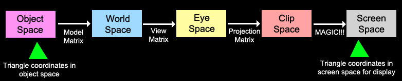
Next, we'll look at the big picture. You feed this vertex shader (program on the GPU responsible for manipulating vertex data) data: vertex coordinates in object space, the object's model matrix, the view matrix, and the projection matrix. Now that your vertex shader has this information it starts processing it for display on the screen. First it multiplies the vertex coords by the object's model matrix. Now it knows where each vertex in that object rests in the virtual world. Next it transforms these points using the view matrix. This moves the points around as if the virtual camera were the new center of the universe. Some points may end up behind the camera or otherwise be outside its viewing range. These details are not worried about in eyespace. Instead, these eye space coordinates are transformed by your projection matrix. The coordinates are now in clip space and ready for the rest of the process that will turn them into 2d points on the screen.
Matrix Math
The process of applying the matrix transforms (multiplying matrices by coordinates) takes place in the shader. We haven't talked about the language that these shaders are written in yet (GLSL), but rest assured that multiplying these matrices and coordinates there is very easy. What isn't very easy is doing matrix math in your C program; you gotta learn a little bit and implement the functions yourself. We will mostly use linear algebra to build the matrices that are sent to the vertex shader. Remember that you need to create the model matrix for each object in your world. You also need to define the view and projection matrices that will create a viewport into that world. All of these matrices that we will be talking about are 4 rows by 4 columns (4x4). They are represented in code as an array of 16 floats. OpenGL expects you to use column-major ordering although it is not strictly necessary, I still recommend it. This means that the first 4 floats in your flat array represent the values of the first column of the matrix (starting in the top left and going toward the bottom left).
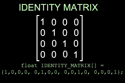
When building a matrix, it is usually helpful to start with an identity matrix. The identity matrix is simply a 4x4 filled with zeros with a diagonal line of ones running from its top-left to its bottom-right. It is a very specific arrangement and should be hardcoded because it will never change. The identity matrix essentially means "don't change anything". If you multiply the vertices that comprise your 3d pencil model by an identity matrix, the points will remain unchanged. If the pencil's model matrix were an identity matrix, that would mean that the pencil rests at the center of world space and is not rotated in any way. Creating an identity matrix is the matrix math equivalent of "starting at zero". By performing various operations on an identity matrix, we can build a more useful transformation matrix that describes how objects relate to each other in this virtual world.
Matrix Translation
Translation is just a fancy math geek way to say "movement". When you slide your TV remote across the coffee table to your right, you are actually translating it. Translation is pretty easy to do with matrices. When you create a translation matrix, you are building it from 3 pieces of information: X translation, Y translation, and Z translation. These inputs define (for each axis) how far and in what direction the object will move if it is transformed by the resulting matrix.
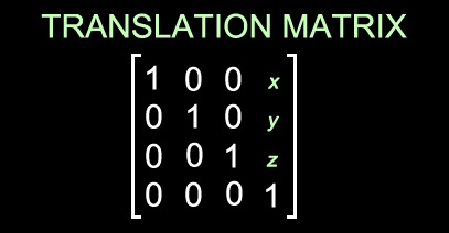
All you have to do to build a translation matrix is place the translation components into some of the cells of an identity matrix. For example, if you want the matrix to move an object 2 units to the left, just insert -2.0 into the top-right cell of the matrix. For the Y axis, its the cell directly below that (still in the 4th column). For the Z axis, you just go down one more (4th column, 3rd row). When the coordinates of the vertices that make up that object (for example: a TV remote) are multiplied by this matrix, they will be translated or moved.
void translationMat(float *dest, float x, float y, float z)
{
 		dest[0] = 1;  dest[4] = 0;  dest[8] = 0;  dest[12]= x;
		dest[1] = 0;  dest[5] = 1;  dest[9] = 0;  dest[13]= y;
		dest[2] = 0;  dest[6] = 0;  dest[10]= 1;  dest[14]= z;
		dest[3] = 0;  dest[7] = 0;  dest[11]= 0;  dest[15]= 1;
}
Matrix Rotation
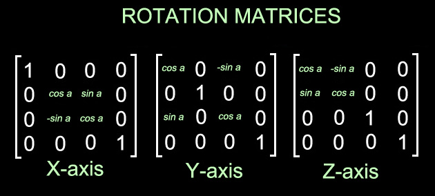
Matrices can also be rotated, things are little more tricky here, but not too bad. The image above will be your best guide, or you can grab my code below. I have no idea how matrix rotation actually works because trigonometry is scary stuff. What I do know is that you can calculate these rotation matrices for each axis using an angle. Then you transform your vertex coordinates using the resulting matrix. The center of this rotation will be the origin of whatever space your vertices are in. Object rotations are therefore best done in object space. This means that if you want to rotate a pencil, you should create that object's model matrix using one of these rotation functions. That way, when the vertex shader transforms the pencil's object space coordinates using its model matrix; the result will be a rotated pencil.
void rotMatX(float *dest, float a)
{
    copyMat(dest, IDENTITY_MATRIX);

    dest[5] = cos(a);
    dest[6] = -sin(a);
    dest[9] = sin(a);
    dest[10]= cos(a);
}

void rotMatY(float *dest, float a)
{
    copyMat(dest, IDENTITY_MATRIX);

    dest[0] = cos(a);
    dest[2] = sin(a);
    dest[8] = -sin(a);
    dest[10]= cos(a);
}

void rotMatZ(float * dest, float a)
{
    copyMat(dest, IDENTITY_MATRIX);

    dest[0] = cos(a);
    dest[1] = sin(a);
    dest[4] = -sin(a);
    dest[5]= cos(a);
}
Combining Transformations
Often, you will want to move a 3d object in several ways. You may want to make a pencil float and spin at the same time, for example. Imagine the player's viewpoint in a first person shooter; it needs to glide and rotate around as the player moves. By now, you should know that a single transformation matrix can store information about both of these transformations. We'll focus on the pencil and its model matrix, but the same logic applies to the view matrix in the FPS example. We know how to build a translation matrix that can be applied to the pencil to make it float. We also saw how to construct a rotation matrix that can make the pencil spin. We need a way to combine these two transformations into one. We can do this through matrix multiplication. Yes, this is the same matrix multiplication that made your homework take forever. You said to yourself "We are never going to use this." Well, guess what, you were wrong (and so was I). Luckily, we can multiply two matrices together programmatically.
First, remember the following...WHEN MULTIPLYING MATRICES, THE ORDER MATTERS. What I mean is that MatrixA = MatrixB * MatrixC is not the same thing as MatrixA = MatrixC * MatrixB. The order in which you multiply matrices together will have a very real effect on how the resulting transformation matrix behaves. In the floating/spinning pencil example, getting it wrong will probably result in a pencil that flies around in a circle (instead of spinning in place while floating). So, you multiply your make-it-float translation matrix by your make-it-spin rotation matrix. The result of this operation will be a new transformation matrix. Apply this to your pencil object and you should get the behavior that you want. What's really neat is that you can keep stacking these transformations and still end up with a single matrix at the end. As long as you pay attention to the order that you multiply the matrices in, you can create any placement/orientation/scaling combination that you want and store it one transformation matrix.
void copyMat(float dest[], float src[])
{
    int c;
    for(c = 0; c < 16; c++)
        dest[c] = src[c];
}

void multMat(float *matDest, float *matA, float *matB)
{
    float dest[16];
    int c, d, e;

    for(c = 0; c < 4; c++)
        for(d = 0; d < 4; d++)
            for(e = 0, dest[c + d * 4] = 0; e < 4; e++)
                dest[c + d * 4] += matA[c + e * 4] * matB[e + d * 4];

    copyMat(matDest, dest);
}